Ground loops can be a real nuisance in HVAC data acquisition systems because they are hard to spot. Most of the time they do no harm but they can cause unpredictable problems years after the installation!
What is a Ground Loop?
A ground loop is formed when there is more than one conductive path between the “ground” terminals on two or more pieces of equipment. The conductive loop forms a large loop antenna that picks up interference currents easily. The larger the loop the more interference; if you are using the building’s steel frame for your ground, then the loop can be as large as the whole building. The resistance in the ground wires turns the interference currents into voltage fluctuations in the ground system. The ground is no longer stable; therefore the signals you are trying to measure which are referenced to that ground are also unstable and inaccurate.

Ground Mythology
A universal concept taught in technical schools and engineering colleges is that “ground” is always zero volts, can infinitely soak up electrical current and harmlessly dissipate the current instantly. A perfect ground, however, is a laboratory abstraction and does not exist in the real world.
Real grounds are conductors, so there is a certain amount of resistance to electrical current between all grounding points. This resistance can change with humidity, temperature, connected equipment and many other variables. The resistance can always allow an electrical voltage to exist across it. Large currents running through grounds will cause voltage drops in the ground conductors and will take time to dissipate.
Michigan State University’s Agricultural Engineering Department measured ground resistances at electrical power service entrances and found that building grounds may vary by up to 2 volts. In fact, the National Electric Code (NEC) allows the ground to vary by up to 2.5% of the branch circuit voltage or 3 volts RMS for a 120VAC circuit (see “References” below for more on Michigan State U. study and the NEC code).
Understanding that perfect grounds do not exist in the real world is the first step to correcting ground loop interference when it occurs. If you remember that each ground in a building is at a different and arbitrary “zero” potential, then you can design proper grounding systems.
If Grounds Are So Flawed, Why Ground At All?
Grounds are needed for two reasons, safety and safety.
NEC Article 250 specifies that the isolated secondaries of step-down power distribution transformers be grounded at the building power entrance. The ground is a copper rod driven a minimum of 8 feet into the ground. The NEC requires that the structural steel frame, water pipes and other major metal objects be connected to the building entrance ground. If a wire’s insulation breaks down or a wire inadvertently comes loose and contacts a metal object, large fault currents flow from the power distribution transformer to ground. These excessive currents open fuses and circuit breakers preventing equipment from being at a higher potential than a nearby sink or building structure. If the ground connection in the power distribution panel becomes disconnected for any reason, then the building power entrance ground at the transformer assures that excessive fault current flows, opening fuses and circuit breakers. Protecting the building from fire and its occupants from electrocution is the main function of the power distribution ground system.
The second safety issue is to keep equipment within its normal operating voltage range. Most modern Direct Digital Controllers (DDC) will operate correctly without a ground connection anywhere. The only catch is that the non-grounded equipment may build up large static charges due to insulation leakage. The first person that comes along and touches the equipment gets a very nasty shock. If the static charge gets high enough, it will discharge to the nearest conductor at a lower potential. The instantaneous discharge currents can reach several thousand amperes and destroy the electronic components of the system. Grounding the system lets the charges dissipate without damage.
Signal Interference From Ground Loops
Ground loops allow electrical and magnetic interference to create noise voltage sources. These voltage sources add to the signal being measured and are indistinguishable from the proper signal. The controller, not knowing that it is reading an improper value, performs an improper control action. This can result in uncomfortable conditions for the occupants. It can also drive the mechanical equipment into an oscillation, causing the equipment to wear out prematurely.
Signal Interference From Magnetic Induction
The primary sources of these noise problems are Magnetic Induction and Ground Imbalance.
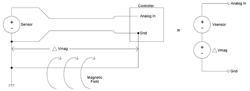
Any loop of conductive material will form a single turn transformer if a magnetic field is present, and magnetic fields are possible wherever AC voltage is used. Magnetic fields are created by AC voltage flowing down a wire, by motors or by florescent lights. In very low level circuits, dangling wires moving in the earth’s magnetic field can even cause problems. The magnetic field causes current to flow in the loop of conductive material, and the loop’s resistance produces a voltage from that current flow.
The more intense the magnetic fields, or the higher the frequency of the magnetic fields, the greater the current that flows. Ohm’s law states that current times resistance equals voltage. So the greater the current flow, the larger the voltage noise source.
The left side figure below shows a ground loop under the influence of a magnetic field. The magnetic field causes electrical current to flow in the ground loop. The resistance of the loop converts the current flow into a voltage source between the ground input of the controller and the ground terminal of the sensor as shown in the right side figure below.

Signal Interference From Ground Imbalance
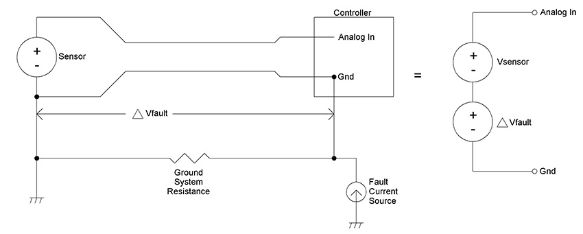
Electrical loads can vary across a building, placing different currents into the ground system. If a large current is flowing in the ground system, and a sensor is placed in a circuit with a ground that also has a ground loop, then the voltage difference between the two ground points will be added to the signal.
The figure below at left shows a fault current source injecting current into the ground system. If, as in the Michigan State study, the voltage across the ground system is two volts, then a fault voltage of two volts is added to the sensor’s signal as shown in the figure below at right.

Closing
Ground loops can render the best control system ineffectual. If you believe that ground loops may be causing a problem with your HVAC/R system, call your BAPI representative or download the BAPI Application Note: Avoiding Ground Loops from our website at www.bapihvac.com
References
ANSI/NFPA 70, National Electric Code 2002 – National Fire Protection Association
Construction Strategies for Minimizing Stray Voltage on Dairy Farms, Michigan State University
Henry Ott, Noise Reduction Techniques in Electronic Systems, 2nd edition, Wiley and Sons, NY, NY, 1988
Michigan State Univ. Study & the NEC Code
Michigan State University’s Agricultural Engineering Department measured ground resistances at electrical power service entrances and found:
“If a service panel ground rod is driven 8 feet into moist earth that is not real sandy, the resistance between that ground rod and the earth might be as low as 20 ohms. Assume that when power is being used in the building, one-tenth of an ampere of the neutral current flows to earth at the ground rod. A basic electrical law called Ohm’s law states that current times resistance is voltage. Multiplying the ground rod current (0.1 amperes) and the ground rod resistance (20 ohms) results in 2 volts. If one probe of a voltmeter touches the ground rod and the other probe of the voltmeter is pushed into the earth as far away from the ground rod as the leads will reach, the meter will read approximately 2 volts.”
NEC Code
The National Electric Code (NEC) does not help with the problem either. Article 250 of the NEC requires branch circuits to be grounded to the closest local building ground wherever the branch circuit panels are in the building. Figures in Article 250 show grounding to building steel. As pointed out in the Michigan State article, building “grounds” may vary according to their measurements by up to 2 volts. The NEC Article 647.4(D), (Article 647 is titled Sensitive Electronic Equipment) allows the ground to vary by up to 2.5% of the branch circuit voltage or 3 volts RMS for a 120VAC circuit.


